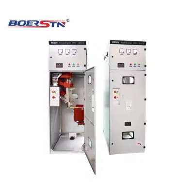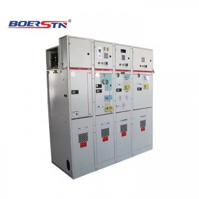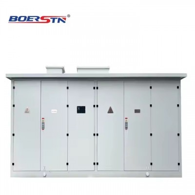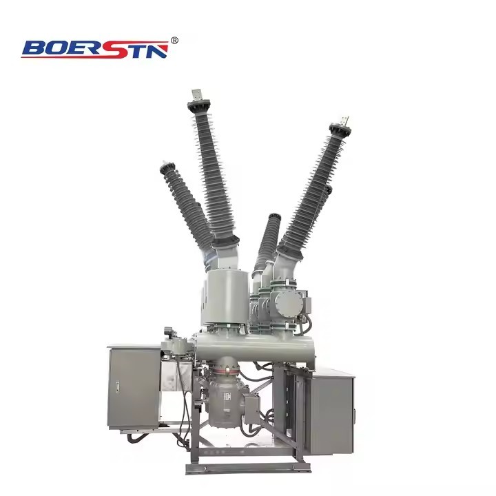

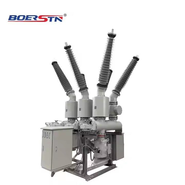
Three Phase High Voltage SF6 Hybrid Gas Insulated Switchgear HGIS 145kV 2500A SF6 Circuit Breaker
| Price | ¥3.00/Piece |
| Min quantity | 10Piece |
| Quantity | 20000Piece |
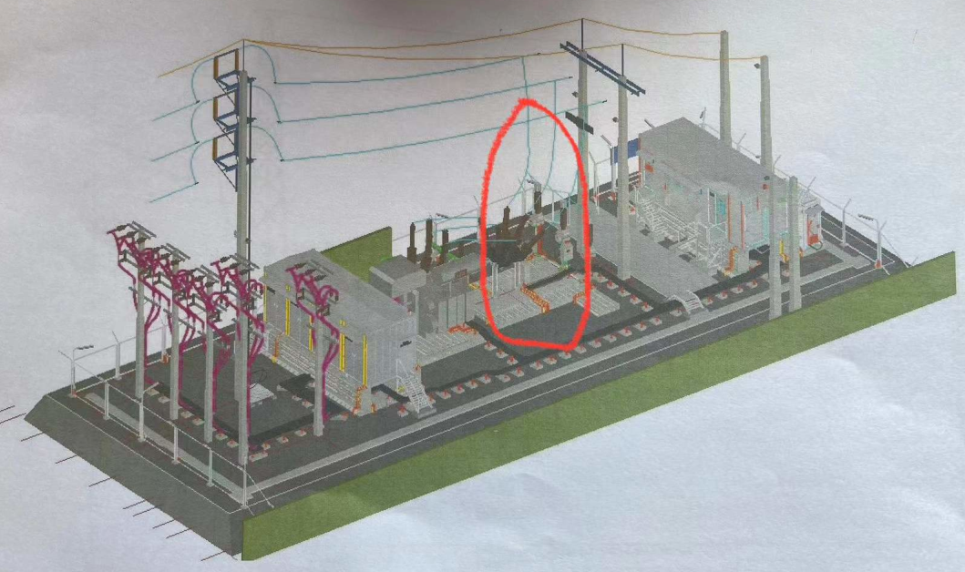
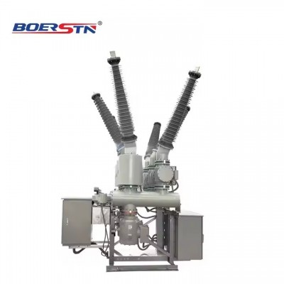
ZHW-145 Hybrid Gas Insulated Switchgear (hereinafter referred to as HGIS) belongs to
three-phase AC high-voltage transmission equipment and is in three-phase box type structure. The
core part circuit breaker adopts self-energy arc-extinguishing principle equipped with the spring
mechanism. It is applicable to 145kV electric system, and used to cut off the load current and fault
current, convert and isolate lines, measure current and voltage, and protect overvoltage, etc. It
assembles all the primary equipment in the substation within the grounding metal shell, except the
power transformer, and then constitutes an integral as per the main wiring requirements of users,
and then it is filled with SF 6 gas as the insulation and arc-extinguishing medium. It connects to the
external power grid via lead-out bushing or cable connection devices.
1. When comparing ZHW-145 HGIS with conventional power station, it has many advantages,
such as small floor area, reliable operation, long repair cycle, excellent electrical properties, and
no external influence. It is a popular high-voltage electrical product in urban power grid
transformation and heavy pollution areas and highly reliable substations
2. GIS can meet the requirements of the national standard GB7674-2008 Gas Insulated
metal-Enclosed Switchgear with Rated Voltage of 72.5kV and Above, and the international
standard IEC 62271-203: 2003 high-voltage switchgear and control equipment—Part 203 Gas
Insulated metal-enclosed Switchgear with Rated Voltage of 72.5kV and above.
Operating environmental conditions
a) Installation site:: outdoor
b)Ambient environment: -40°C to + 40°C
c)Altitude: (merely for the lead-out bushing) : less than 1000m
d) Icing thickness: 10mm
e) Pollution grade: III and IV
f) Earthquake intensity:AG5
g) Wind speed: less than 34m/s;
h) Places without flammable, combustible, chemical corrosion and violent vibration.
Specifications
HGIS Technical Data
| No. | Description | Unit | Parameter | |
| 1 | Rated voltage | KV | 145 | |
| 2 | rated current | incoming | A | 2500 |
| outgoing | A | 2500 | ||
| 3 | Rated power frequency withstand voltage(1 minute) | kV | 275 | |
| 4 | Rated lighting impulse withstand voltage(peak) | KV | 650 | |
| 5 | Rated short-time withstand current | KA | 40 | |
| 6 | Rated short - circuit closing current | KA | 104 | |
| 7 | Rated short-time withstand current and duration | KA/S | 40/3 | |
| 8 | Rated peak withstand current | KA | 104 | |
| 9 | Auxiliary and control circuit short-time power frequency withstand voltage,1 min | KV | 2 | |
| 10 | SF 6 Gas Pressure(20℃) | Mpa | 0.65 | |
| 11 | SF 6 Gas Leakage | %/YEAR | ≤0.1 | |
| 12 | SF 6 Moisture | Handover acceptance value | μL/ | ≤150 |
| Allowable values for long-term operation | μL/ | ≤300 | ||
| 13 | Partial Discharge | Test Voltage | kV | 1.1×145/ 3 |
| Every Chamber | PC | ≤5 | ||
| 14 | Power Supply | Control circuit | V | DC 110 |
| auxiliary circuit | V | AC 220 | ||
| SF6 circuit breaker | ||||
| 15 | Type Number | NGCB | ||
| 16 | Structure | Horizontal | ||
| 17 | Number of circuit breaker | pcs | 1 | |
| 18 | Rated current (incoming and outgoing) | A | 2500 | |
| 19 | Main Circuit Resistance | μΩ | ≤60 | |
| 20 | Temperature Rise | A | 1.0 I | |
| 21 | Rated frequency 1min withstand voltage | KV | 275 | |
| 22 | Rated lightning impulse withstand voltage peak | KV | 650 | |
| 23 | Rated short - circuitbreaking current | Isc | KA | 40 |
| First pole to clear factor | 1.5 | |||
| 24 | Rated short - circuit closing current | KA | 104 | |
| 25 | Rated short-time withstand current | KA/s | 40/3 | |
| 26 | Rated peak withstand current | kA | 104 | |
| 27 | Breaking time | MS | ≤60 | |
| 28 | Close and Open time | MS | ≤60 | |
| 29 | Open Time | ms | ≤40 | |
| 30 | close time | ms | ≤100 | |
| 31 | Reclosing time without current gap | ms | ≥300 | |
| 32 | Open and close average speed | Open Speed | m/s | 5.0±0.5 |
| close speed | m/s | 2.8±0.5 | ||
| 33 | Non-synchronism | ms | ≤3 | |
| 34 | Close Non-synchronism | ms | ≤4 | |
| 35 | Mechanical life | times | 10000 | |
| 36 | Rated operating sequence | O–0.3s–CO–180s–CO | ||
| 37 | Site opening and closingwith transformer no-loadcapacity | Transformer no-load capacity | MVA | 40 |
| No - load excitation current | A | 0.5 - 15 | ||
| Test Voltage | KV | 145 | ||
| Operating sequence | 10×O 10×(CO) | |||
| 38 | Site Charging current testof open and closetransmission power lineno-load capacity | Test current | A | It depends on the length of transmission line. |
| test voltage | KV | 145 | ||
| Operating sequence | 10×(O-0.3s-CO) | |||
| 39 | Capacitive currentopening and closing test | Test current | A | Line:50;Cable:160 |
| Test voltage | 1.4×145/ 3 | |||
| C1 : LC1 and CC1 : 24×O ; LC2 and CC2:24×CO C2 : LC1 and CC1 : 48×O ; LC2 and CC2 : 24×O and | C2 | |||
| 40 | Open and close abilityunder near - faultcondition | L90 | KA | 36 |
| L75 | KA | 30 | ||
| L60 | KA | 24 | ||
| Operating sequence | O-0.3s-CO-180s-CO | |||
| 41 | Out of phase closing andBreaking capacity | breaking current | kA | 10 |
| test voltage | KV | 2.5×145/ 3 | ||
| Operating sequence | No.1:O-O-O No.2:CO-O-O | |||
| 42 | SF 6 Gas Pressure | rated | MPa | 0.65 |
| alarm | MPa | 0.62 | ||
| lock | MPa | 0.6 | ||
| 43 | Mechanism Type | Spring | ||
| 44 | Operating | Three pole mechanism | ||
| 45 | Motor Voltage | VDC | 110 | |
| 46 | Closing operating | Rated Operating voltage | VDC | 110 |
| Operating voltage permissible range | 85%~110% | |||
| Number of Coil | 1 | |||
| Coil Inrush Current | 5 | |||
| Coil Steady - state current | 2.5A | |||
| 47 | Opening operating | Rated Operating voltage | VDC | 110 |
| Operating voltage permissible range | 65%~110% | |||
| Number of Coil | 2 | |||
| Coil Inrush Current | A | 5 | ||
| Coil Steady - state current | A | 2.5 | ||
| 48 | Heater | voltage | VAC | 220 |
| power | W | 50 | ||
| 49 | Auxiliary contact | nO. | Pair | 10NO+10NC |
| breaking capacity | 2.5A | |||
| 50 | Spring mechanism | Energy storage time | S | ≤20 |
Disconnector switch
| 1 | Type Number | NGDS | ||
| 2 | Rated Current | A | 2500 | |
| 3 | Main Circuit Resistance | μΩ | ≤40 | |
| 4 | Temperature Rise Current | A | 1.0 I | |
| 5 | Rated frequency 1min withstand voltage | KV | 275 | |
| Rated lightning impulse withstand voltage peak | KV | 650 | ||
| 6 | Rated short-time withstand current and duration | kA/s | 40/3 | |
| 7 | Rated peak withstand current | KA | 104 | |
| 8 | Open and close duration | OPEN Time | ms | ≤4000 |
| close time | ms | ≤4000 | ||
| 9 | Mechanical stability | time | 5000 | |
| 10 | Opening and closing small capacitor current value | A | 1 | |
| 11 | Opening and closing small inductor current value | A | 0.5 | |
| 12 | Open and close busbarconversion currentcapacity | Conversion current | A | 1600 |
| Conversion voltage | V | 10 | ||
| Breaking time | time | 100 | ||
| 13 | Operating mechanism | type | Electric and manual | |
| motor voltage | VDC | 110 | ||
| control voltage | VDC | 110 | ||
| Allowable voltage range | 85%~110% | |||
| Operation method | Three pole mechanism | |||
| 14 | Auxiliary contact | Number | pair | 10NO+10NC |
| breaking capacity | 2.5A | |||
Drawings
