Product Information


Title goes here.
Installation:
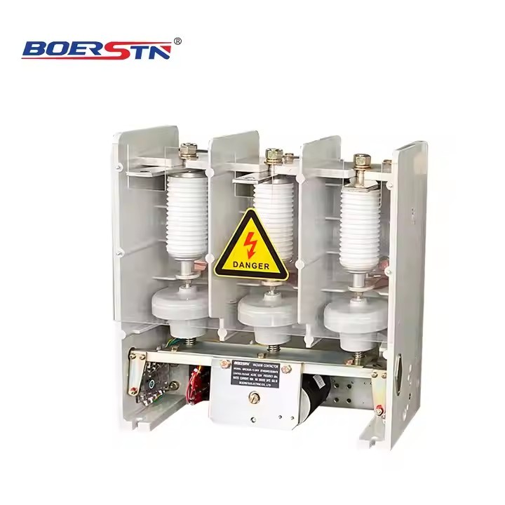
6 . 1 . 1 Mounting hole is drilled on mounting plate based on dimensions in Fig. 1 ,2;
6 . 1 .2 It shall be fixed with M8 bolt and lock washer, mounting inclination not exceeding 15 degrees;
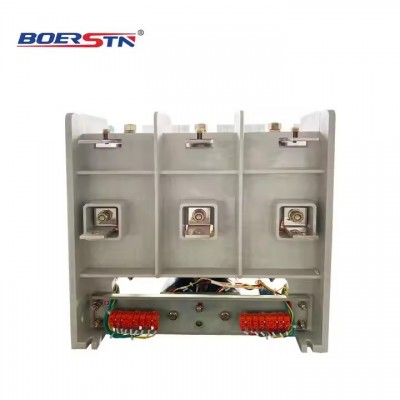
6 . 1 .3 Wires of control power supply and auxiliary contact are properly connected to secondary input terminal;
6 . 1 .4 Copper busbar is properly connected to main loop .
6 . 1 .5 Operating voltage and current of main loop and control loop of contactor shall be in accordance with the
specifications , in avoidance
of damage;
6 .2 Check and adjustment
6 .2 . 1 For contactor in service , its vacuum degree shall be checked once every half a year ( power frequency withstand voltage
method). Power frequency withstand voltage of vacuum interrupter of 7 .2kV shall be more than 15kV;
6 .2 .2 Routine check , lubrication and cleaning are performed once a year.
6 .2 .3 Check if auxiliary contact is well contacted. In case of bad contact , it shall be maintained or replaced ;
6 .2 .4 After operating for 100 ,000 times , it shall be thoroughly checked.
6 .2 .5 If vacuum interrupter is seriously damaged or burned , it shall be replaced at once . After replacement with new vacuum
interrupter, contactor shall be overall adjusted. Methods: Charge electromagnetic
system of contactor to close vacuum interrupter, and check interval between over-travel adjusting nut and washer with self- made
insert , which shall be between 1mm and 1 .5mm , with three phases being consistent . Measure the distance L1 between the plane
of guide sleeve on vacuum tube and the surface of flexible connector at the end of guide rod with measuring tools ( inside
calipers) , and then interrupt and release contactor. Then , adjust separation adjusting screw, to make the distance L2 between
the plane of guide sleeve and the surface of flexible connector at the end of guide rod is equal to the sum of L1 and rated
separation between contacts , (while adjusting separation , three phases need to be repeatedly debugged , to guarantee synchronism
of three phases) , and tighten each adjusting nut , thus separation and over-travel are adjusted up (See Fig1) .
6 .2 .6 Operation tests within the following voltage range shall be performed for the adjusted contactor:
a . Open and close the contactor for 5 times with 85% rated control supply voltage;
1. Open and close thecontactor for 5 times with110% rated control supply voltage;
c . If rated control supply voltage is lower than 30% , contactor must be released and try twice .
Storage and Transportation
7 . 1 Contactor shall be stored in well-ventilated environment with relative humidity less than 85% , and room



 verified

